I received the PCBs for the fan controller a few days ago, and I soldered them up today. The purpose of the fan controller is to take the PWM signal from the ECU (open source) and convert that to a PWM signal for the fan. Since the fan only runs in one direction, there's only one MOSFET needed, and the circuit becomes pretty simple.
The circuit is simple - pull-up resistor on the input signal, one N-channel MOSFET to do the switching, a MOSFET driver to drive this high-capacitance FET, and flyback/transient protection.
The assembly process involves a few easy steps: 1) apply solder paste to the PCB. 2) place components on PCB. 3) Reflow solder. 4) Rework (if necessary).
Step 1: Apply solder paste
 |
| Apply solder paste out of syringe if you don't have a stencil. For these large pitch parts, you can apply a dot of solder to each pad. For smaller pitch parts (.5mm or smaller), you will probably have to lay down a line of solder paste. |
Step 2: Place components:
 |
| Place components carefully using tweezers or a vacuum extension |
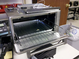
Step 3: Place in reflow oven (in this case a Cuisinart toaster over - works great!) Monitor the temperature using a thermocouple. Typically I bring it up to 160C, let it soak for 60 seconds, then bring it to the reflow temperature (~200C) and check for visual confirmation of reflow.
Step 4: No rework necessary in this case. With these large pitch parts, as long as you're careful with solder paste application, the yield is typically very high.


No comments:
Post a Comment